AdvancedComputer Organisation & Architecture (COA) · Lesson 10 of 10 · Updated ·
Control Unit Design — Micro-operations, Hardwired vs Microprogrammed Control, Horizontal and Vertical Microinstructions
Lesson 1 said the control unit "directs everything", and lesson 4 contrasted hardwired and microprogrammed control in two lines. This lesson shows what the control unit actually produces — a sequence of control signals — and how a microprogrammed control unit stores those sequences as a tiny program. GATE often asks for the size of a control word or control memory, so we finish with those numericals.
1. Control signals and micro-operations
Inside the CPU, data moves between registers, memory and the ALU over internal buses. Each move is switched on by a control signal — for example PC_out (put the PC on the bus) or MAR_in (load the MAR from the bus).
One elementary step, such as copying one register to another, is called a micro-operation. We write it in register transfer notation:
| Notation | Meaning |
|---|---|
| MAR ← PC | copy the program counter into the memory address register |
| MDR ← M[MAR] | read memory at the address in MAR into the memory data register |
| PC ← PC + 1 | increment the program counter |
| ACC ← ACC + MDR | add MDR to the accumulator |
Every instruction is executed as a short sequence of such steps. For the fetch cycle:
| Step | Micro-operations | Control signals |
|---|---|---|
| T1 | MAR ← PC | PC_out, MAR_in |
| T2 | MDR ← M[MAR], PC ← PC + 1 | Read, MDR_in, PC_inc |
| T3 | IR ← MDR | MDR_out, IR_in |
Micro-operations in the same step must not conflict — two registers cannot drive the same bus at once. That is why MDR ← M[MAR] and PC ← PC + 1 can share T2 (they use different paths), but PC_out and MDR_out could not.
2. Two ways to build a control unit
| Hardwired | Microprogrammed | |
|---|---|---|
| Signals come from | logic gates driven by a step counter, the opcode and flags | words read from a control memory |
| Speed | faster | slower (one control-memory read per step) |
| Changing or adding instructions | redesign the circuit | rewrite the microprogram |
| Design effort for a large instruction set | very high | manageable |
| Typical use | RISC processors | classic CISC processors; complex instructions in some modern CPUs |
A hardwired unit is like a fixed traffic-signal circuit: very fast, but any change means rewiring. A microprogrammed unit is like a traffic signal run by a stored timetable: change the timetable, and the behaviour changes.
3. Inside a microprogrammed control unit
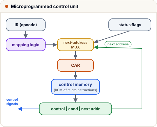
- Control memory — usually a ROM holding microinstructions. A group of microinstructions that carries out one machine instruction is a microroutine; all of them together form the microprogram.
- Control address register (CAR) — holds the address of the next microinstruction, like a PC for the microprogram.
- Microinstruction register (also called the control data register) — holds the word just read.
- Next-address logic (sequencer) — decides the next CAR value: the next word in order, a jump given in the next-address field (possibly only if a status flag is set), or the start of a microroutine found by mapping the opcode.
A microinstruction typically has three fields:
control field | condition select | next address
Here is a tiny control memory in Python that runs the fetch cycle and then an ADD instruction:
# address -> (control signals active in this step, next address)
CONTROL_MEMORY = {
    0: (["PC_out", "MAR_in"], 1),                     # MAR <- PC
    1: (["Read", "MDR_in", "PC_inc"], 2),             # MDR <- M[MAR], PC <- PC + 1
    2: (["MDR_out", "IR_in"], "map"),                 # IR <- MDR, then jump by opcode
    10: (["IR_addr_out", "MAR_in"], 11),              # ADD: MAR <- address part of IR
    11: (["Read", "MDR_in"], 12),                     # MDR <- M[MAR]
    12: (["MDR_out", "ALU_add", "ACC_in"], 0),        # ACC <- ACC + MDR, back to fetch
}
MAPPING = {"ADD": 10}                                 # opcode -> first micro-instruction

car, opcode = 0, "ADD"
for step in range(6):
    signals, nxt = CONTROL_MEMORY[car]
    print(f"CAR={car:2}  {', '.join(signals)}")
    car = MAPPING[opcode] if nxt == "map" else nxt
print("next CAR:", car)
CAR= 0  PC_out, MAR_in
CAR= 1  Read, MDR_in, PC_inc
CAR= 2  MDR_out, IR_in
CAR=10  IR_addr_out, MAR_in
CAR=11  Read, MDR_in
CAR=12  MDR_out, ALU_add, ACC_in
next CAR: 0
After fetch (addresses 0–2), the mapping sends control to the ADD microroutine at address 10. When ADD finishes, the next address is 0 — fetch the next instruction.
4. Horizontal vs vertical microinstructions
How do we encode the control field?
- Horizontal — one bit per control signal. Any combination of signals can be on at the same time, and no decoding delay is added. But the words are wide.
- Vertical — signals are split into groups that are never active together (mutually exclusive, for example "which register drives the bus"). Each group is stored as a short code and passed through a decoder. Words are much narrower, but decoding adds delay and limits parallelism.
A group of n signals needs ⌈log₂(n + 1)⌉ bits — the "+ 1" is for the code that means "none of these".
| Horizontal | Vertical | |
|---|---|---|
| Control field width | = number of signals | much smaller |
| Parallel signals | any combination | at most one per group |
| Decoders needed | no | yes |
| Speed | faster | slightly slower |
| Control memory size | larger | smaller |
5. Control-word size numericals
Question. A CPU has 48 control signals. The control memory has 1,024 words, and branches can test any one of 8 status conditions. Find the width of a horizontal microinstruction, and the control-field width if the 48 signals form 5 mutually exclusive groups of 7, 15, 3, 20 and 3 signals.
- Next-address field: log₂ 1024 = 10 bits.
- Condition select: log₂ 8 = 3 bits.
- Horizontal control field: 48 bits. Total = 48 + 3 + 10 = 61 bits.
- Vertical: ⌈log₂ 8⌉ + ⌈log₂ 16⌉ + ⌈log₂ 4⌉ + ⌈log₂ 21⌉ + ⌈log₂ 4⌉ = 3 + 4 + 2 + 5 + 2 = 16 bits. Total = 16 + 3 + 10 = 29 bits.
from math import ceil, log2

def horizontal_width(signals, cm_words, conditions):
    addr = ceil(log2(cm_words))           # next-address field
    cond = ceil(log2(conditions))         # which flag to test
    return signals + cond + addr, (signals, cond, addr)

def vertical_control_bits(groups):
    # each group of mutually exclusive signals needs log2(size + 1) bits
    # (+1 because "no signal from this group" must also be encoded)
    return [ceil(log2(g + 1)) for g in groups]

total, parts = horizontal_width(signals=48, cm_words=1024, conditions=8)
print("horizontal word:", total, "bits =", " + ".join(map(str, parts)))

groups = [7, 15, 3, 20, 3]               # 48 signals in 5 exclusive groups
bits = vertical_control_bits(groups)
print("vertical control field:", bits, "=", sum(bits), "bits instead of", sum(groups))
horizontal word: 61 bits = 48 + 3 + 10
vertical control field: [3, 4, 2, 5, 2] = 16 bits instead of 48
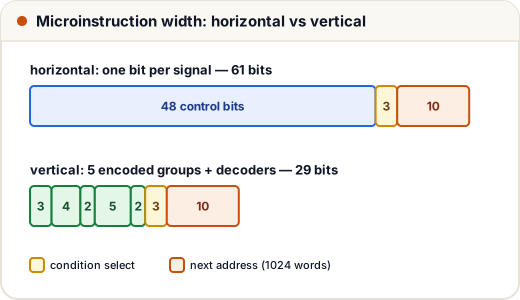
Control memory size = number of words × word width. Horizontal: 1,024 × 61 = 62,464 bits. Vertical: 1,024 × 29 = 29,696 bits — less than half.
Exam variations to watch for:
- Some questions add 1 to the condition count for "unconditional branch"; follow the wording.
- If the question says "the signals are encoded in groups", use ⌈log₂(n + 1)⌉ per group unless it says a group never needs a "none" code; then ⌈log₂ n⌉.
- If the control memory size is given in words, the next-address field is log₂ of that number.
Common mistakes
- Confusing the CAR with the program counter — the PC points to machine instructions in main memory; the CAR points to microinstructions in control memory.
- Forgetting the "none" code when encoding a vertical group — 15 signals fit in 4 bits (16 codes), but 16 signals need 5 bits.
- Leaving out the condition and next-address fields when asked for the full microinstruction width.
- Saying microprogrammed control is faster — it is more flexible, but hardwired control is faster.
- Putting conflicting micro-operations (two registers driving one bus) in the same step.
Quick recap
- Each instruction = a sequence of micro-operations; each step switches on a set of control signals.
- Fetch: MAR ← PC; MDR ← M[MAR], PC ← PC + 1; IR ← MDR.
- Hardwired: fast, rigid (RISC). Microprogrammed: control memory + CAR + sequencer, flexible (CISC).
- Microinstruction = control field | condition select | next address.
- Horizontal: 1 bit per signal, wide and fast. Vertical: ⌈log₂(n + 1)⌉ bits per group, narrow, needs decoders.
- Control memory size = words × word width.