Computer Organisation & Architecture (COA) · Lesson 1 of 8 · Updated ·
How a Computer Works — Von Neumann Architecture, CPU, Registers, Buses and the Instruction Cycle
Every program you write — Python, Java, C — eventually becomes a sequence of tiny instructions executed by the CPU billions of times a second. Computer Organisation and Architecture (COA) explains how. It's a core subject in B.Tech/BCA/MCA, a regular GATE topic, and the reason some code is 10× faster than other code that looks the same.
1. Architecture vs organisation
| Computer architecture | Computer organisation | |
|---|---|---|
| Question | what the machine does, as seen by a programmer | how it's built to do that |
| Examples | instruction set, data types, addressing modes, number of registers | control signals, cache design, pipelines, bus widths |
| Analogy | the car's controls (steering, pedals) | the engine and gearbox underneath |
Two processors can share an architecture (e.g. both run x86-64 programs) with very different organisations (different caches, pipelines, speeds).
2. The von Neumann model
Almost every computer follows the stored-program idea of John von Neumann (1945): instructions and data live in the same memory, and the CPU fetches them one after another.
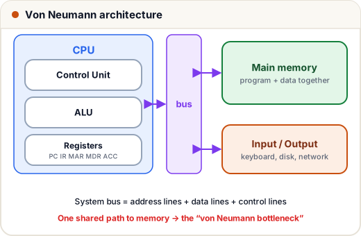
Main parts:
- CPU = Control Unit (CU) + Arithmetic Logic Unit (ALU) + registers
- Memory — holds program and data
- I/O — keyboard, display, disk, network
- System bus — the wires connecting them
The von Neumann bottleneck: instructions and data share one path to memory, so the CPU often waits for memory. Caches (lesson 5) exist largely to fight this. The Harvard architecture uses separate memories/paths for instructions and data — common in microcontrollers, and modern CPUs use it at the cache level (separate instruction and data caches).
3. Inside the CPU
| Part | Job |
|---|---|
| ALU | arithmetic (+, −) and logic (AND, OR, NOT, compare) |
| Control Unit | decodes instructions and sends control signals to everything else |
| Registers | tiny, ultra-fast storage inside the CPU |
The registers you must know:
| Register | Holds |
|---|---|
| PC (Program Counter) | address of the next instruction |
| IR (Instruction Register) | the instruction being executed now |
| MAR (Memory Address Register) | the address to read/write in memory |
| MDR / MBR (Memory Data/Buffer Register) | the data just read from / about to be written to memory |
| ACC (Accumulator) | result of ALU operations (in simple accumulator machines) |
| General-purpose registers | R0, R1, … for operands and results |
| Flags / status register | Zero, Carry, Sign, Overflow bits from the last operation |
| SP (Stack Pointer) | top of the stack (function calls) |
4. Buses
| Bus | Carries | Direction |
|---|---|---|
| Address bus | which memory location / device | CPU → memory/I/O (one-way) |
| Data bus | the actual data | both ways |
| Control bus | signals: read, write, interrupt, clock | both ways |
Address bus width decides addressable memory: with n address lines and byte-addressable memory, the CPU can address 2ⁿ bytes. 16 lines → 64 KB; 32 lines → 4 GB.
for lines in [16, 20, 32]:
    size = 2 ** lines
    print(f"{lines} address lines -> {size:,} bytes = {size // 1024:,} KB")
16 address lines -> 65,536 bytes = 64 KB
20 address lines -> 1,048,576 bytes = 1,024 KB
32 address lines -> 4,294,967,296 bytes = 4,194,304 KB
(The 20-line case is the original 8086's famous 1 MB limit.)
5. The instruction cycle: fetch → decode → execute
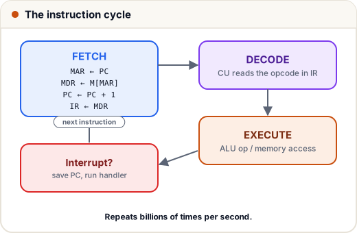
In register-transfer notation (used in exams):
| Step | Micro-operations |
|---|---|
| Fetch | MAR ← PC; MDR ← Memory[MAR], PC ← PC + 1; IR ← MDR |
| Decode | control unit examines the opcode in IR, fetches operand addresses |
| Execute | e.g. for ADD X: MAR ← X; MDR ← Memory[MAR]; ACC ← ACC + MDR |
| Interrupt check | if an interrupt is pending, save PC and jump to the handler |
6. A tiny CPU in Python
Let's build a toy accumulator machine with 4 instructions and watch the cycle run. The program computes marks1 + marks2 and stores it.
memory = {
    0: ("LOAD", 10),    # ACC <- M[10]
    1: ("ADD", 11),     # ACC <- ACC + M[11]
    2: ("STORE", 12),   # M[12] <- ACC
    3: ("HALT", None),
    10: 78, 11: 92, 12: 0,
}
PC, ACC = 0, 0
while True:
    MAR = PC                      # fetch
    MDR = memory[MAR]
    PC = PC + 1
    IR = MDR
    opcode, addr = IR             # decode
    if opcode == "HALT":          # execute
        print(f"HALT  -> M[12] = {memory[12]}")
        break
    if opcode == "LOAD":
        ACC = memory[addr]
    elif opcode == "ADD":
        ACC = ACC + memory[addr]
    elif opcode == "STORE":
        memory[addr] = ACC
    print(f"{opcode:5} {addr} -> ACC = {ACC:3}, PC = {PC}")
LOAD  10 -> ACC =  78, PC = 1
ADD   11 -> ACC = 170, PC = 2
STORE 12 -> ACC = 170, PC = 3
HALT  -> M[12] = 170
Real CPUs do exactly this — just with hundreds of instructions, many registers, and billions of cycles per second (a 3 GHz clock = 3 × 10⁹ ticks per second; one instruction may take one or several cycles).
7. Performance basics
CPU time = Instruction count × CPI × Clock cycle time (CPI = average Clock cycles Per Instruction).
instructions = 2_000_000
cpi = 1.5
clock_hz = 2e9
cpu_time = instructions * cpi / clock_hz
print(f"CPU time = {cpu_time * 1000:.2f} ms")
print(f"MIPS = {instructions / (cpu_time * 1e6):.0f}")
CPU time = 1.50 ms
MIPS = 1333
To make a program faster you can reduce instructions (better algorithm/compiler), reduce CPI (better organisation, pipelining) or raise the clock.
Common mistakes
- Confusing MAR (an address) with MDR (the data).
- Saying PC holds the current instruction — it holds the address of the next one.
- Forgetting that the address bus is one-way and the data bus two-way.
Quick recap
- Architecture = what the programmer sees; organisation = how it's built.
- Von Neumann: program and data share memory → bottleneck; Harvard separates them.
- CPU = ALU + CU + registers (PC, IR, MAR, MDR, ACC, flags, SP).
naddress lines → 2ⁿ addressable locations.- Cycle: fetch (MAR←PC, MDR←M, PC++, IR←MDR) → decode → execute → interrupt check.
- CPU time = IC × CPI × cycle time.